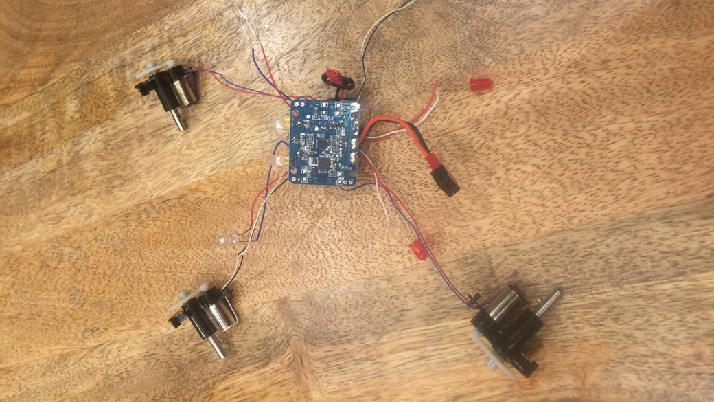
I decided to go for the full-break method of investigating the electronics, and while it worked out well to start, it's looking iffy going forward. After some early success looking at the chips on top of the board in the last post, I'm running into some more trouble with the bottom of the board.
For one, the text on the integrated circuits is a little less clear with less obvious branding. The easier to read of the two parts just has a part number, and the other one has a blurry logo that's hard to pin down and text that is relatively murky. I haven't been able to make much headway, but in the process I did learn that the 3 pin 2312 is probably a MOSFET rated to about 20 volts.
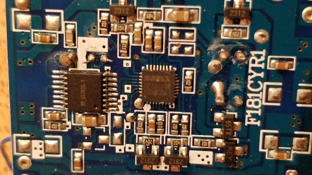
Of somewhat interesting note, the antenna from the other side of the board
appears to connect via a via to the 20_GG7R2S 1 board.
The rest of the 3 digit numbered parts appear to be resistors of various values.
The first two digits are multiplied by 10 to the power of the last digit. For
example, 100 corresponds to 10 * 10^0 = 10 Ohm and 332 corresponds to
33 * 10^2 = 3.3 kOhm.
I also found a surface mount codebook for deciphering the codes that manufacturers put on their tiny chips. More mildly interesting than useful in this case. It hasn't seemed to lead to anything too exciting.
I think that the short and boring conclusion now is that the board consists of an IMU and a microcontroller for reading it, and then the quadcopter is "balanced" by combining the input from the IMU and the controller.
Go watch some AvE!