Mechanically, it's in shambles. What's left in the rubble? I dive into the electronics to figure it out.
Power!
First things first, I wanted to check out the battery voltage to see how it'd fare, and maybe, just maybe, see if it could power an Arduino. It looks like that won't pan out, because from a quick inspection of the power terminals, it looks like the batteries fit into the 4.2V category. Out of complete ignorance of what I should expect out of a battery, I rounded 4.16V up and Googled and got an Adafruit page. I'm not sure exactly how low an Arduino can go and still keep on ticking, but my instinct is that it would be nice if it were in the 5V+ range, but I should expect 3.7V and get a minimum of around 3V. Maybe I'll just fly the quadcopter with both batteries on board and line them up in series.
Looking back at the battery (with the help of the Adafruit link), I can now see that the battery is a 3.7V rated battery with 750 milliamp-hours of current rating and 2.78 Watt-hours of power rating. A quick search of the batteries' serial number indicates that its at least nominally a special part for the quadcopter, but its pretty similar to a lot of other batteries so I bet it could be replaced if needed.
Motivation
The next thing I've been meaning to look into is the motors themselves. The wire leads are absolutely tiny compared with the main leads from the battery pack to the board.
When measuring the resistance across the motor, it comes in at about 1 Ohm. Unfortunately, I don't really have much extra information about the motors by themselves, because the only thing that I can see to distinguish them is two (Chinese?) characters in the plastic back cap of the motor. Of one interesting note, the motors are color coded for clockwise vs counter-clockwise, but silly me, I didn't remember to take note of which ones spun which way before I got started. On with the soup!
In a now somewhat obvious mistake, I bought super-mini-ultra-micro-gigga-fantastic small motors that turned out to be about half the diameter that I thought they were in order to have a backup set/set for building out a new design. After taking the time to measure these motors, they match a standard size of 8.5mm in diameter x 20mm in body length, with an overall length of a little over 25.5mm including the drive gear. This matches the size of some other motors that pop up in an Amazon search for the size; however, I'm not finding ones (yet) with the same markings on the rear as the ones that I have.
Of potential interest, it seems like the "coreless" or "mini-coreless" motors in this size range are used for quadcopters, so my motors are probably coreless. My interest in this was somewhat piqued by my motors magnetically sticking to a pair of calipers, so I figured I could run a test to see if the motors were coreless (with a static magnetic core?) or some other design. I moved a metal spoon (didn't need to abuse the calipers) around the motor, and the gear didn't turn. My hypothesis through random googling appears to be correct, the motor appears to have a static magnet (stator?) and a rotating winding.
Power Electrics: Doing it live
The last step I want to find out about the motors is to check out the voltage that they get when the quadcopter is turned on. It's been a little while since the quadcopter was last run (can I really call it a quadcopter any more? or is it just a battery-powered system for spinning 4 wingdings?) and I've never played around with measuring voltage on motors while they're being powered before, so here goes. What I'm honestly curious to know is if the motors are controlled by changing their voltage or by some sort of PWM. It'll change how I have to "hack" the power chain. If it is changing the voltage, that'll mean I can do some sleuthing of the circuitry to find out what makes the power leveling tick (a buck-boost converter somewhere?)
For my notes, the black motors turn clockwise when you look at the gear.
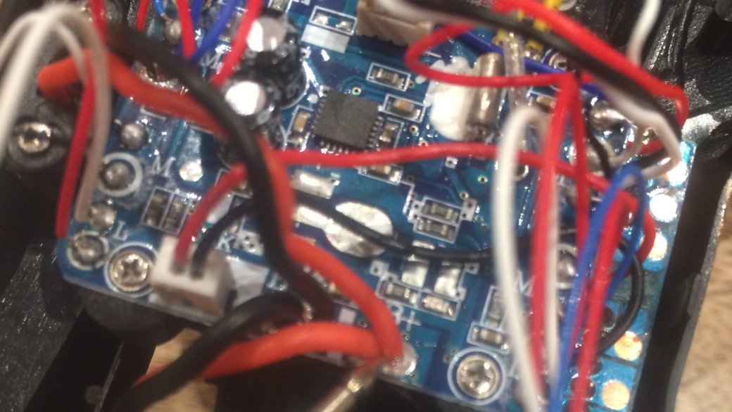
At 5% output power from the controller, the motors are measured at somewhere between 3.6V and 3.7V. Turning it up to 50% and leaving it for a little while actually caused the voltage to be measured at 3.4V. Going up to 100% made it measure at something like 3.3V, which seems to me would indicate that the motors are controlled with PWM and then the voltage drops as current increases and the internal resistance of the motors becomes significant. My original measurement of the resistance didn't change with increasing use, although I've heard that increasing internal temperatures can increase resistance.
For those that were idly curious, the LEDs seem to be powered at about 2V.
At this point, I think I've identified all the major power-in (batteries) and power out (motors, LEDs, camera mount and switch) to the board. What I'd be curious to look at is the power consumption requirements of the motors and LEDs (and maybe the camera too?) as an interesting follow-on analysis project.
kV
Given my home electronics equipment, can I measure the kV? Supposedly its pretty important to understand the (unloaded) behavior of the motor.
There are two methods for identifying the kV of a motor according to this website I just found: - Drive the motor electronically and measure the RPM - Drive the gear with a drill and measure the voltage.
One involves a drill that I don't have, and one involves a data logger that I don't have, but could probably build (yeah! next project!). Not that I don't want to play around with power tools, but building an RPM monitor is actually the sort of project that I've been meaning to take on for a while now.
The basic principle of the data logger method is to power the motor at 100% for a short period of time, then recording RPM, voltage and current. What the link mentions that I don't have (I don't think) is an ESC to make things magically magic their rotations. Instead, I'm going to stick to driving voltage.
There are two additional complications that I can think of here, but I'm going to forge on ahead anyway. First, they recommend using 100% of rated voltage or something, but all I have is 3.7V rated batteries, so I'm going to assume that the motors get the average voltage and work from there. Second, motor specs should include the internal resistance, but I don't have that either (note no specs because I haven't identified the motor yet). Supposedly I can measure this properly, but what I get when I measure it is something around 1 Ohm.
The equation that comes out of this is (defined in Python because me):
def kV(rpm, volts, amps, Rm):
    return rpm / (volts - current * Rm)
I'm going to leave for a bit to dig through my pile of electronics and see if I can't round up those Hall effect sensors I've been staring at for a while and dreaming of using for spying on motors without actually touching the motors.
Casualties for this round: 1 small screw that was supposed to hold on a propeller.