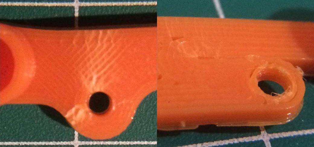
The suspension work continues! The rear design is now printed in a high-shell configuration. This leads to (mostly) nicely aligned filament.

The bottom appears to have printed even more nicely than the top, unfortunately it's likely never going to be the most stressed layer.
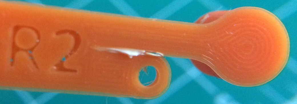
Compressing the rear design here doesn't lead to nearly as bad visual cracking and stresses in the design. It still does appear to flex the beam through a significant bend.
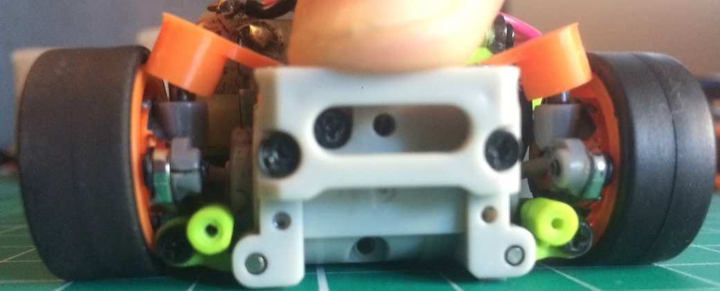
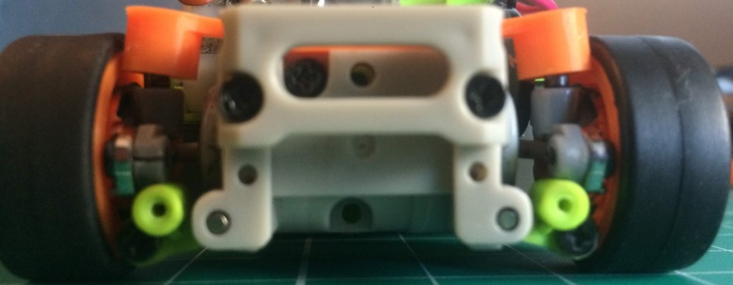
After compression, the suspension appears to relax back to a mostly flat and level position.
Taking a closer look at the suspension, there isn't too much stress damage; however, what little there is appears to come from the outer shells meeting at a gap in the beams. It appears to be about the same 0.2mm gap as between the beams and the mounting hole structure.
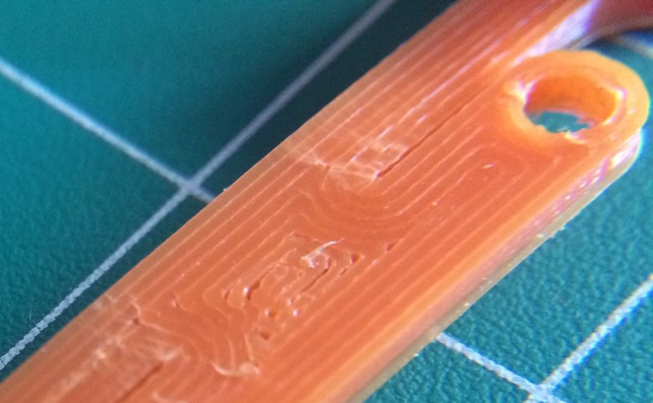
Slightly revised design
The latest design modified the width of the flexing beam to accommodate an integer number of layers to reduce the gaps in the flexing portion of the suspension. This slightly shifted where the arms are relative to the outboard mounting point.
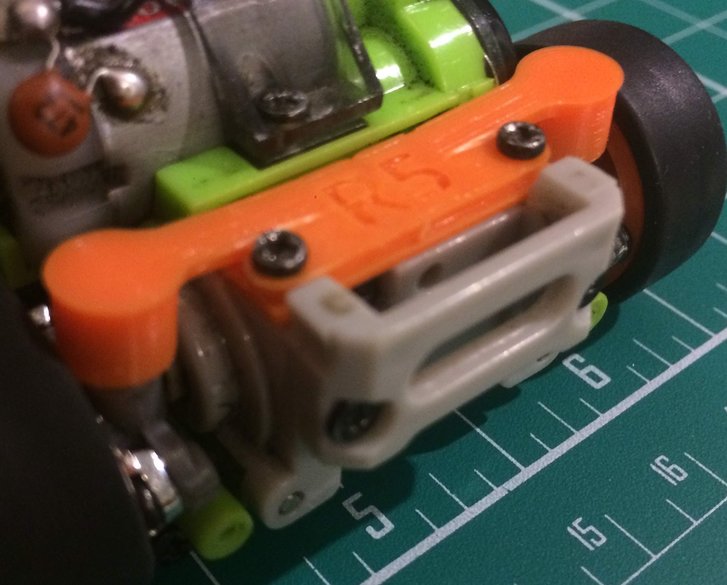
Rendered in CAD
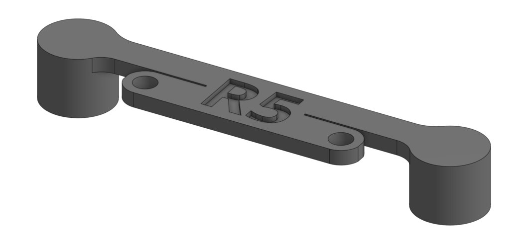
To test out the new design, I repeatedly compressed the suspension through its full range of motion.
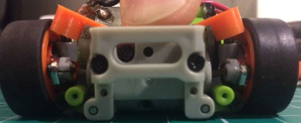
Compared with other designs, it appears to have come out well, especially since this got cycled about twice as much as any other design.
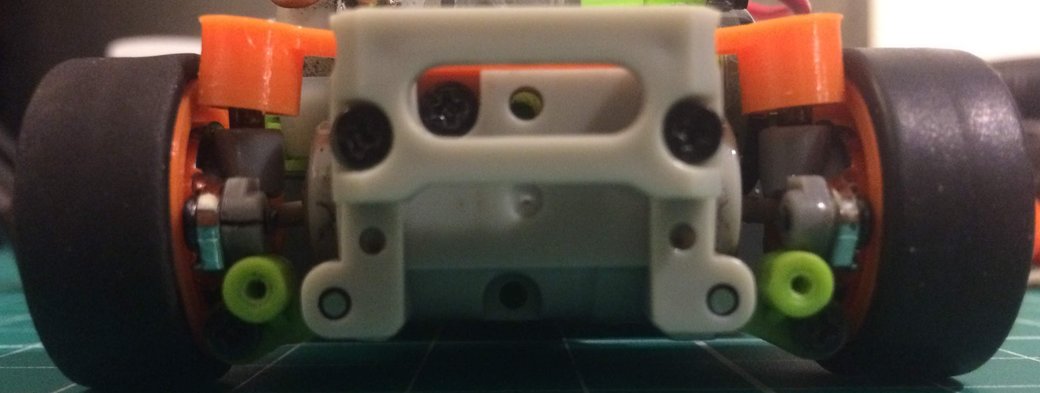
The new design and printing scheme do leave something to be desired for gaps in the center of the part, although that may be fixed by manually setting the infill direction to align with the lateral axis.
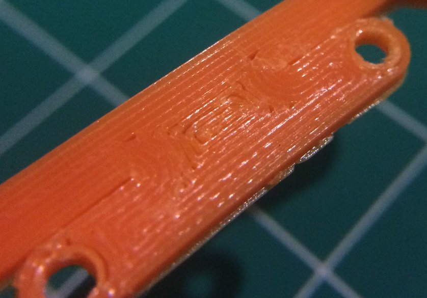
There are small stresses after compressing the suspension many times, but the design appears to be much better than the original rear suspension
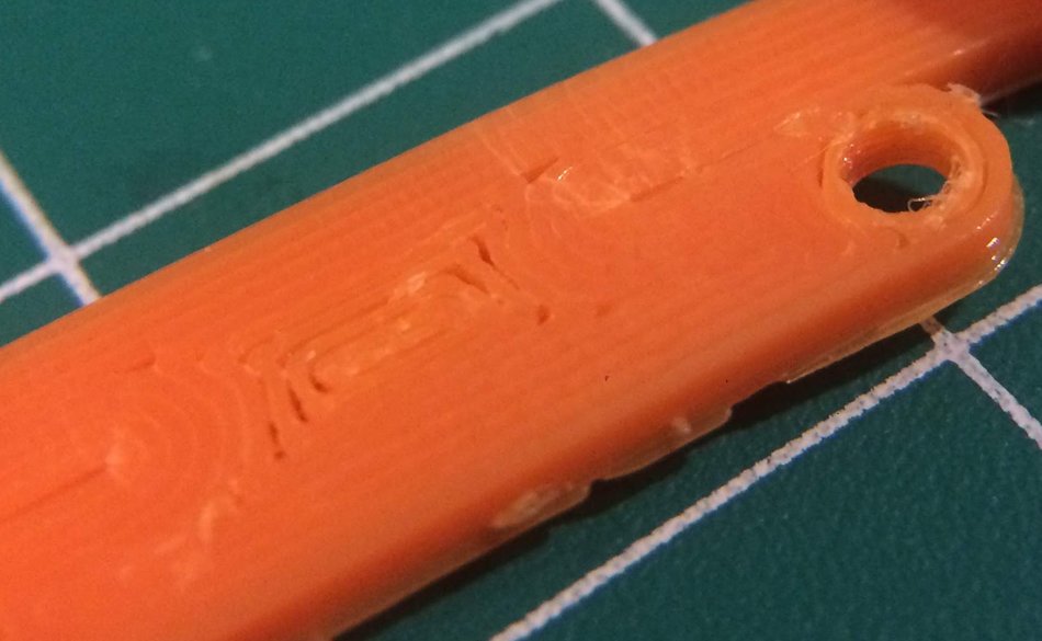
There are small stresses after compressing the suspension many times, but the design appears to be much better than the original rear suspension
