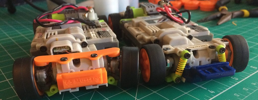
Today focused on simplifying the suspension with a printed design. There's nothing fundamentally wrong with the existing XMods suspension, but I do think there's room for improvement. For example, the existing suspension limits its own range of motion and has relatively poor ground clearance. Also, I've taken it upon myself to replace most of the front clip with printed parts now that I've gone off the deep end and printed the uprights.
Front Suspension
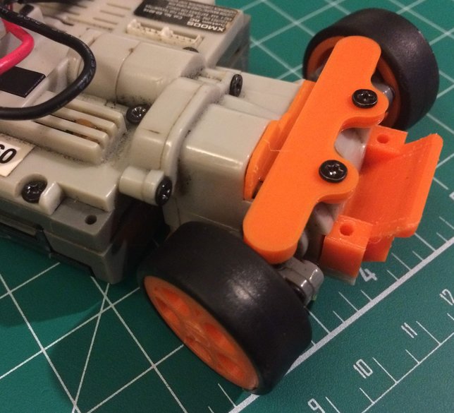
One of the original designs for the front suspension worked fairly well; however, it cracked near the mounting point and was slightly too loose.
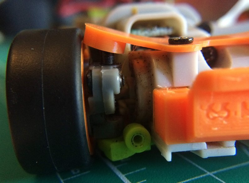
Here the crack can be seen from the top of the suspension.
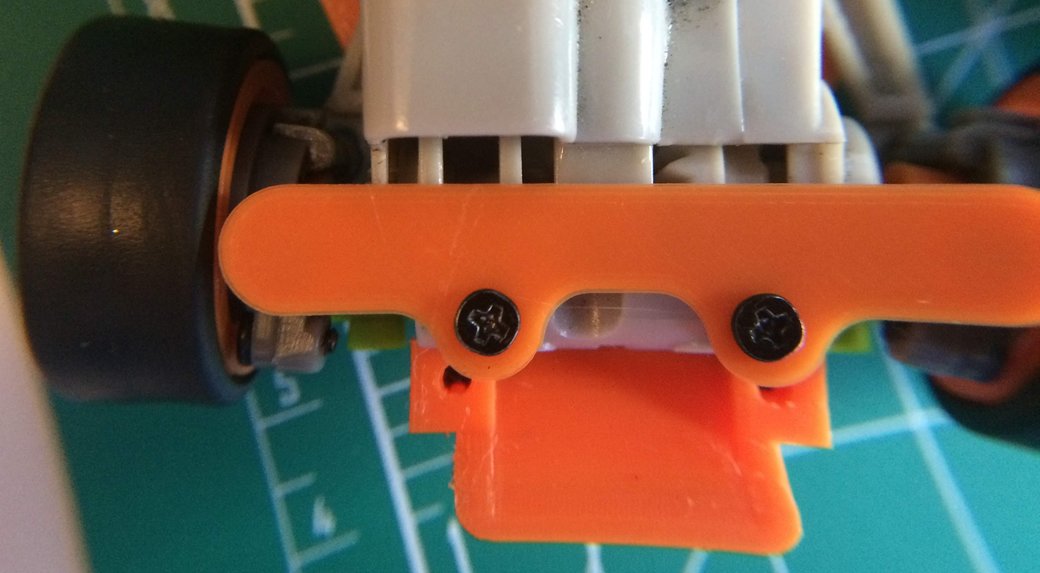
To compensate for that failure, I went up to 1.5mm (15 layers) for the new design, which appears to do the trick and resist plastic deformation. With the new design printed inverted, it is also easier to control the resting ride height (extra layers in the end-cups) and the suspension stiffness (layers between the mounting screws and the wheels.
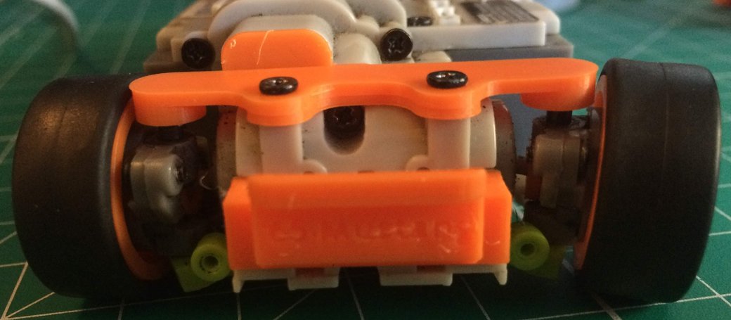
The final design can flex quite a bit; however, it's relatively stiff. Perhaps on a smooth surface the suspension will work, but it's worth investigating softer designs.
For softer suspensions, I think there will be a balance between the suspension's softness and its ability to resist shock loads or stress cycles. Perhaps some combination of changing the cross section may help to provide similar stiffness with reduced effective flexing. This would require increasing the cross section's area moment of inertia, but likely increasing the effective length of the suspension arm.
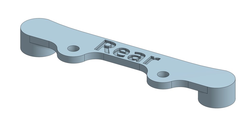
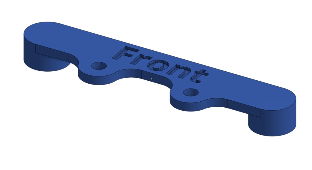
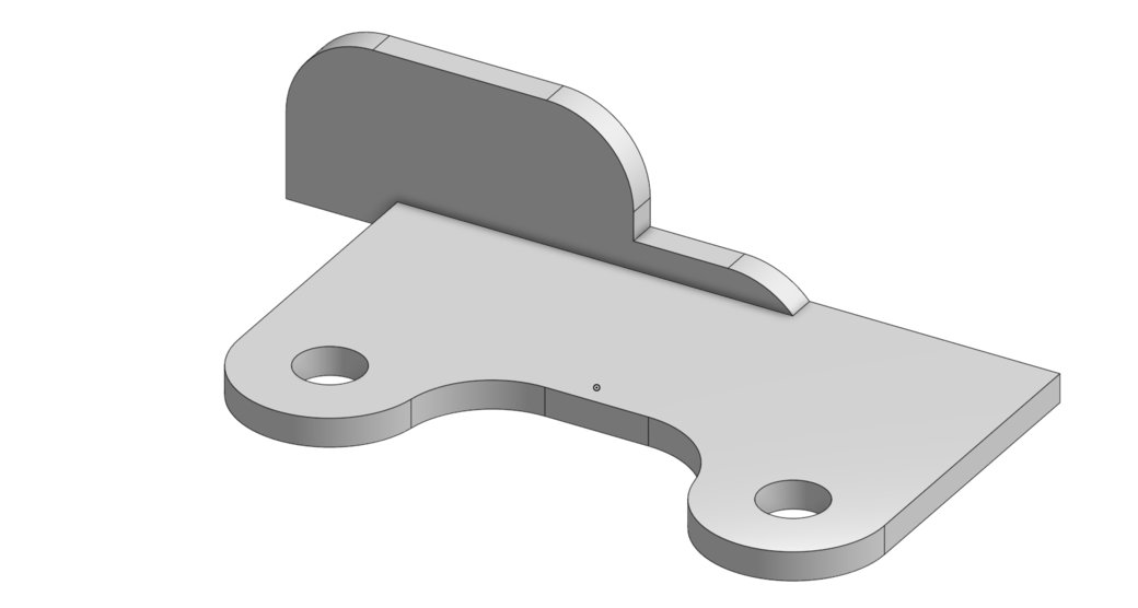
The CAD for the front suspension:
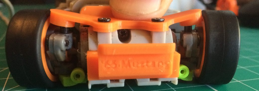
Rear Suspension
The rear suspension has similar space as the front suspension; however, the rear gearbox intrudes on the space, which could affect the rear suspension spring rate. On the other hand, the screw mounts are further out, so there is a reduced space from the mounting screws to the rear uprights. The reduced width might balance out the decreased length to have the end spring rate be similar, or the rear suspension might need an adjustment in the number of layers.
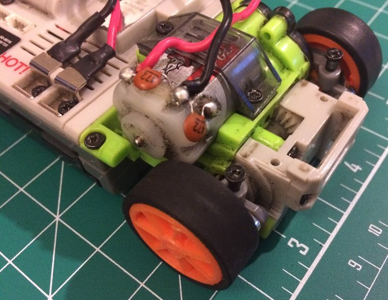
In an unfortunate turn of events, the first print of the rear suspension was too wide for the uprights.
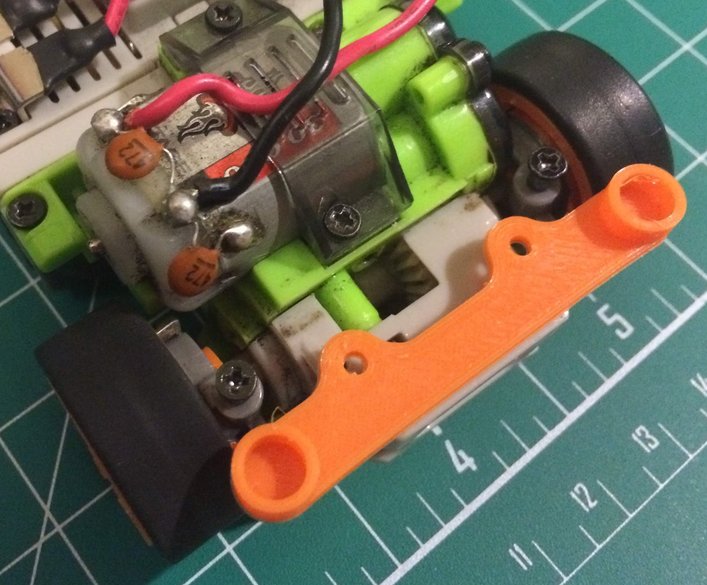
With some adjustment, the rear suspension should be good to go and fit within the packaging constraints.