How small can we get with a functional gear part on a FDM printer? What about packing in extra batteries?
Spinning Bits
First Orbit "Gear"
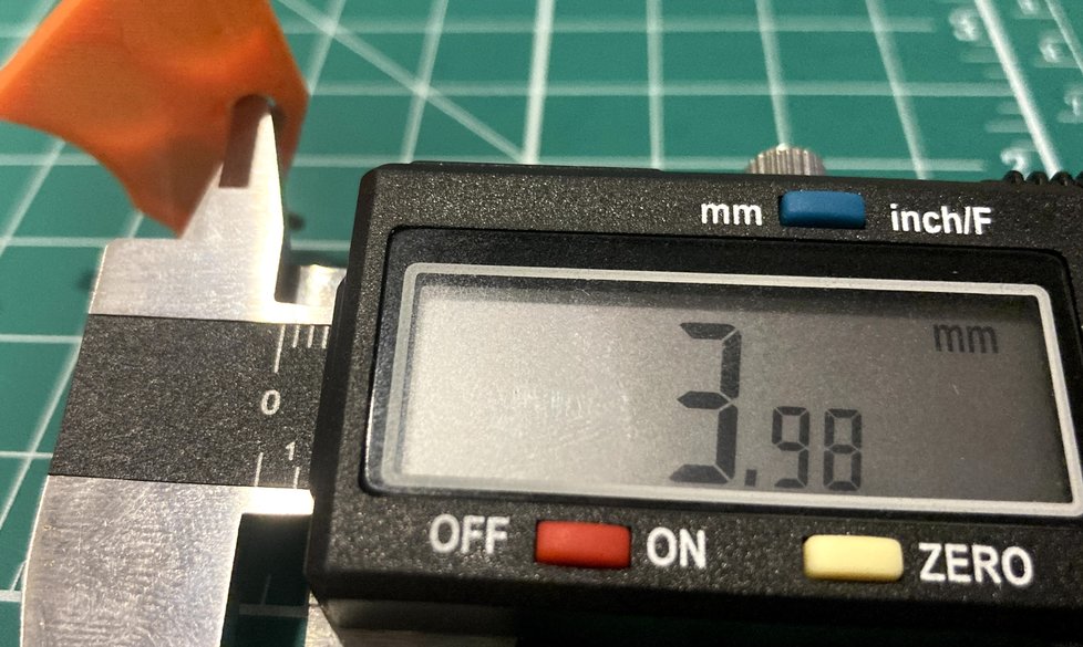
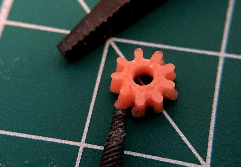
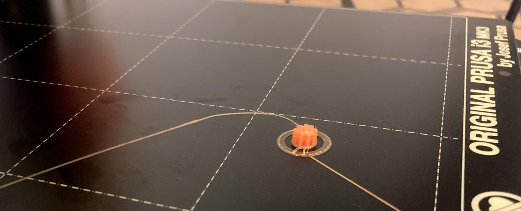
Small Center Gear
Here's a closeup of the center gear for the planet system. It is designed to press-fit onto the motor driveshaft. It printed well (better than the planet gears), but the printer was printing it slightly over size, so the gears weren't meshing well or fitting in the outer gear. Given the scale, I'm going to need to dial in the printer a bit further to get accurate sizing. In this case, even being off by 0.1mm is enough to prevent the design from working.
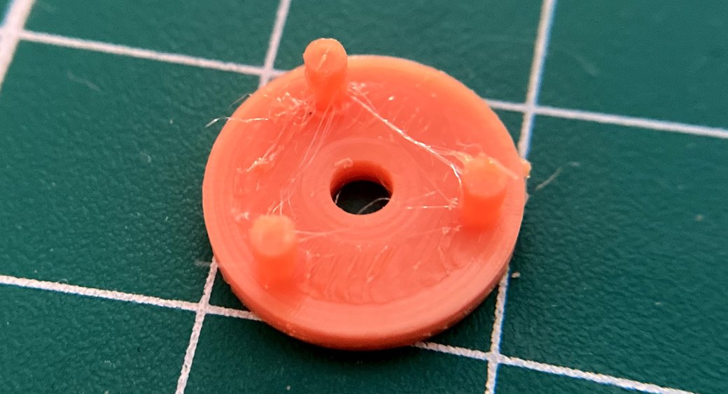
Adjusting? I Meant Damaging
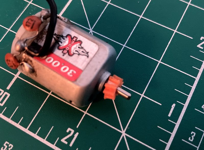
In the process of trying to fit the center gear onto the motor driveshaft, I got a little too enthusiastic with a small file and ended up stretching out one side of the gear. On one hand, it's unfortunate to damage the part, but it's also quick to print another.
Also, I'm starting to think I might be able to do some hacky prints that are slightly too small and then use a mechanical process to slightly stretch the print to its desired size. That would allow me to get closer tolerances than I could get with the printer alone. I'm thinking something analogous to casting and then machining a metal part. The trick will be finding a milling process where I could get the accuracy needed to remove the right amount of material and to make sure that I'm keeping the hole centered.
Internal Gears are Hard
Over many attempts, I've only had mild success printing internal gears. There's been lots of stringing and the parts warp easily.
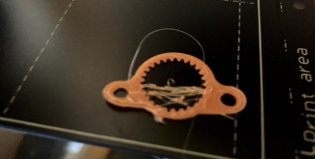
To compensate, I've updated the design for the outer gear of the planetary set to have an additional "brim" within the design of the part both under the teeth and between the outer mounting holes and the central circular area containing the gear. Increased surface area should increase build plate adhesion, leading to a more stable printed dimensions for the final product.
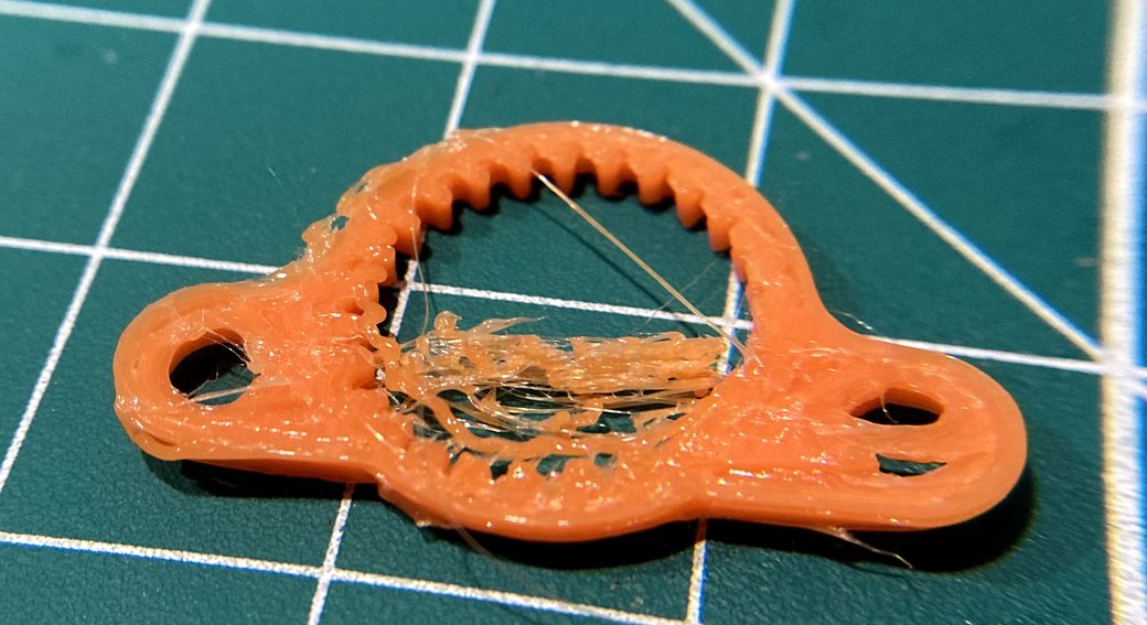
New Design: Built in raft/brim for easier printing
To help the small gears print better, I updated the planetary gear design to include a built in brim for the gears. This will serve a dual purpose: first, it will provide a smooth outline and increased surface area for better print adhesion and, second, it will provide a detent to ensure that the planetary gear system will align axially.
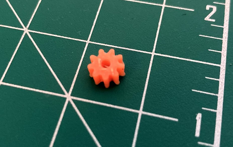
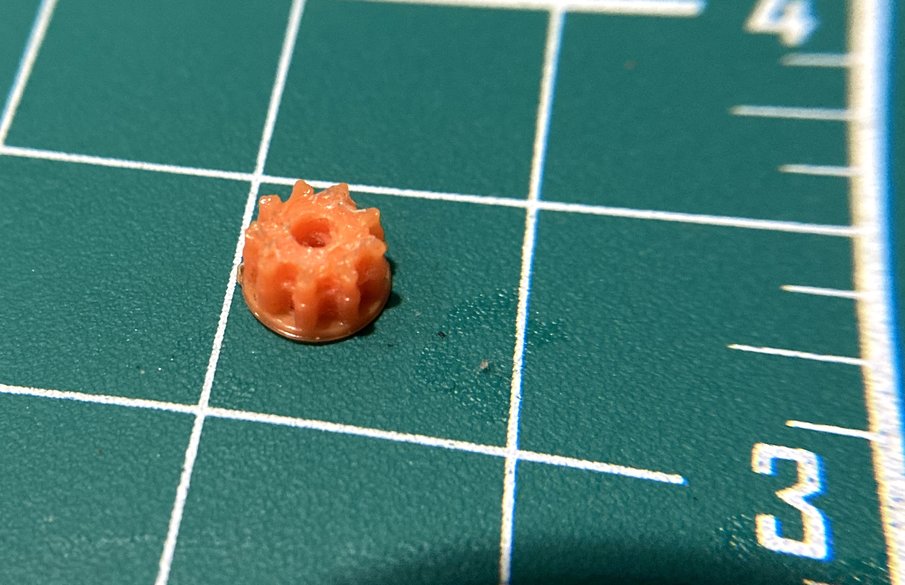
Here's a closeup of the gear on a half-inch grid for scale
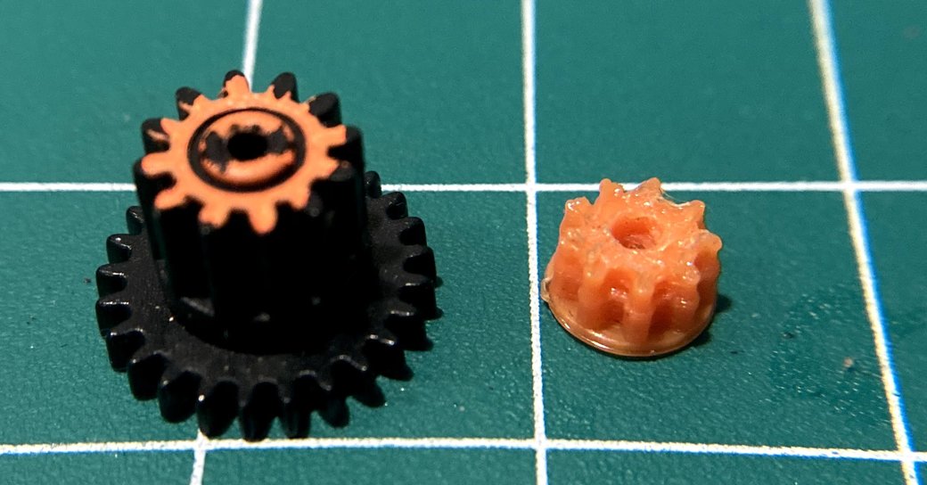
It's not quite a banana, but here's a non-printed gear from the original XMods drivetrain for comparison. The teeth are smaller and more well defined on the XMods part, but the overall size is comparable.
Things that Make the Spinning Bits Spin
Battery Pack Loading
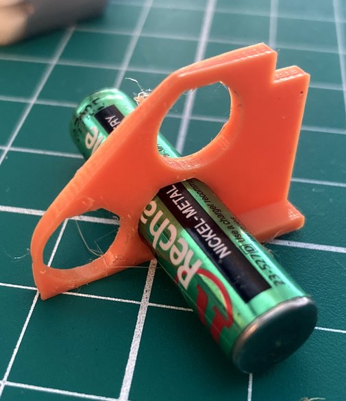
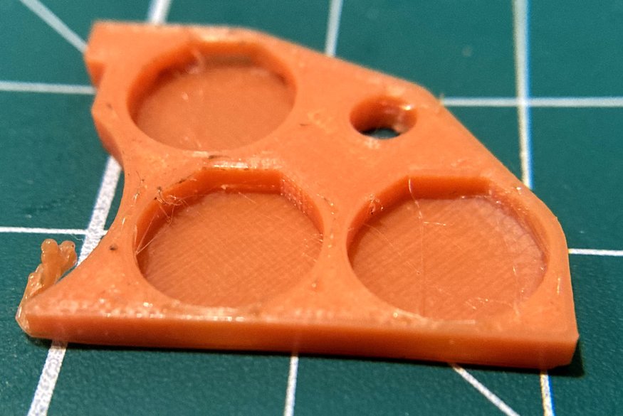
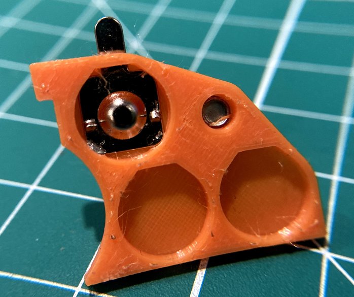
In order to test out clearances for the batteries, I printed out a section cut of the battery pack. It didn't print terribly well, but it still functioned well as a test part.
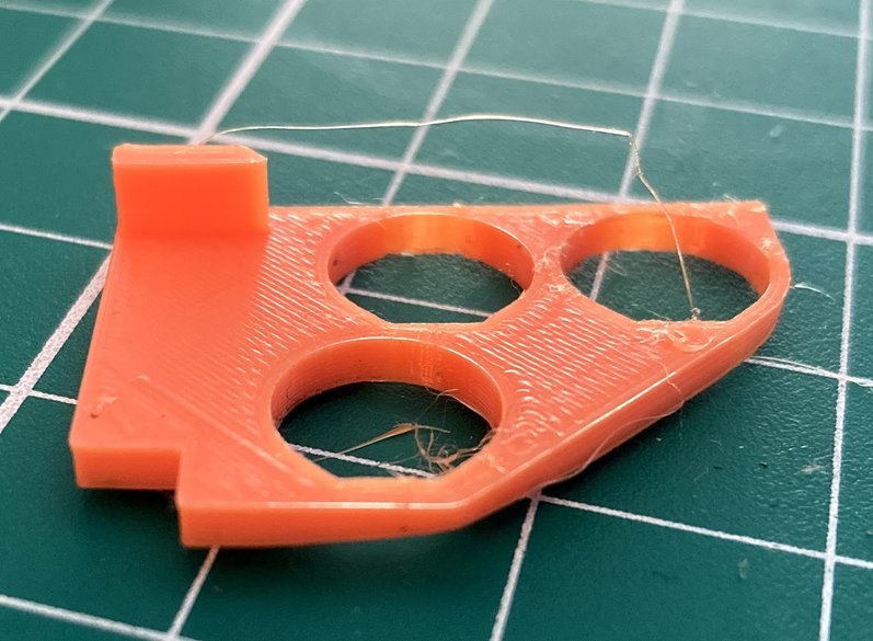
It's easiest to see here, the battery cutouts are non-circular at the top to enable printing vertically. The top of the circle is flattened to a 45 degree angle (from vertical) so that it still closely fits the battery but also would prevent the need for support material.
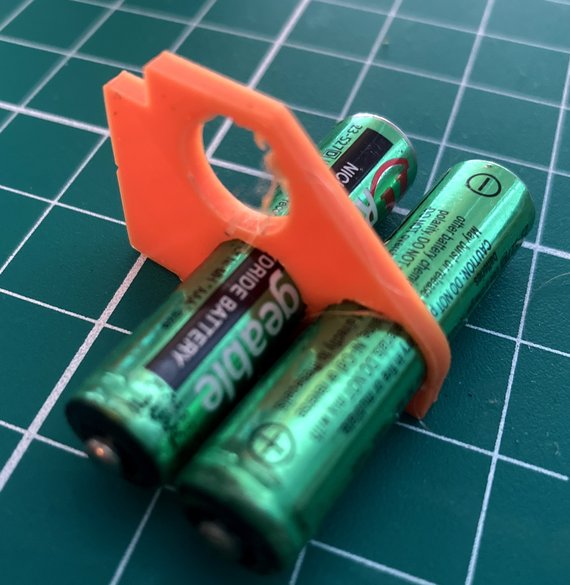
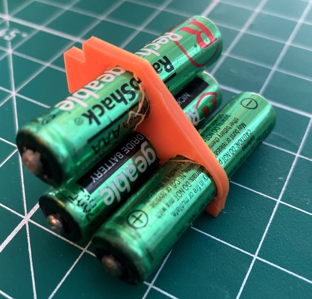
The reason to design a new battery pack is to enable more flexibility in the chassis design and to allow for two extra batteries (and theoretically up to 8). This will provide a combination of better battery life and more power. Or maybe just more power...
Building a Battery Cap
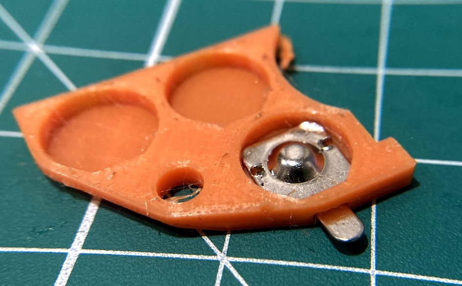
One of the features of the newer design is a battery container with ends that screw on to compensate for variability in the battery dimension, the printed part dimension and the size of the battery contacts.
The first test was to ensure that the battery contacts were thin enough to slide into the slot. Check off at least one aspect of the design that worked on the first try!
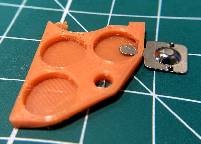
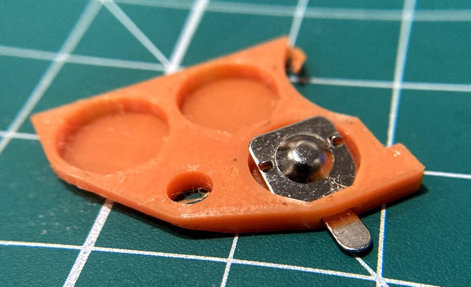
After a little tappy-tap-tap, I was able to get the contact to fit snugly into the battery cap. With a little adjustment, it should be pretty straightforward to find the right combination of tolerances to have the battery contacts snap into place with a little less damage.
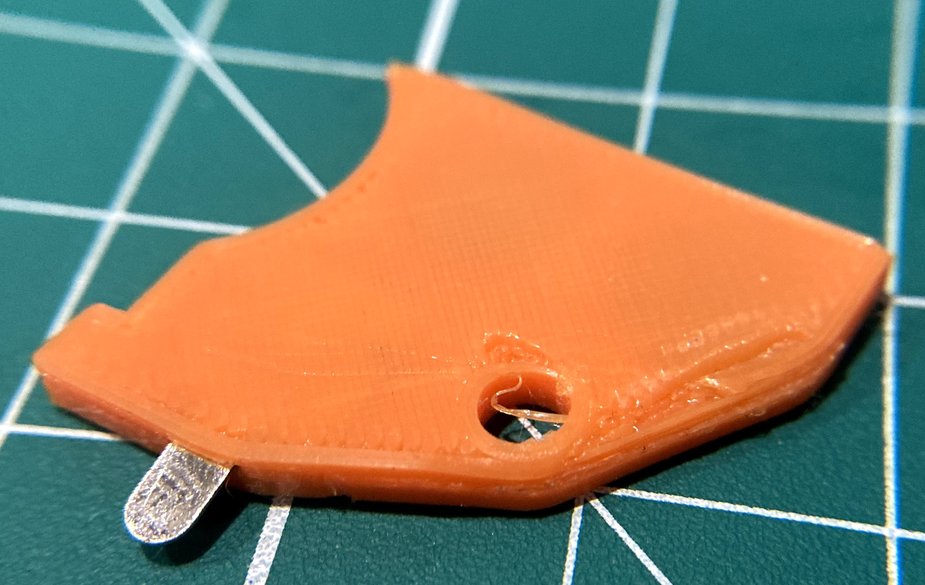
One unfortunate part of the design as it stands today is that it leads to the print detaching partially from the print bed, which warped the (non-critical) face of the part. Mark that as something to save for later when the design is closer to ready.
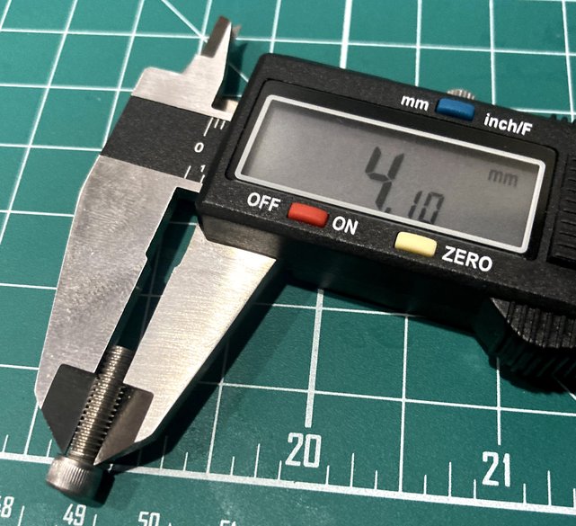
But the Screw (Shoe?) Doesn't Fit
Unfortunately, one aspect I can't ignore is that the tolerances for the screw itself were too small to let it slide through nicely. That's easy to fix with a single change of variable for the next print, but a bit of a bummer that it didn't work as expected here.
Taking out the trusty calipers, we can see that I'm not off by a lot (somewhere in the 0.1 to 0.2 mm range).